Introduction: Geneva Mechanism
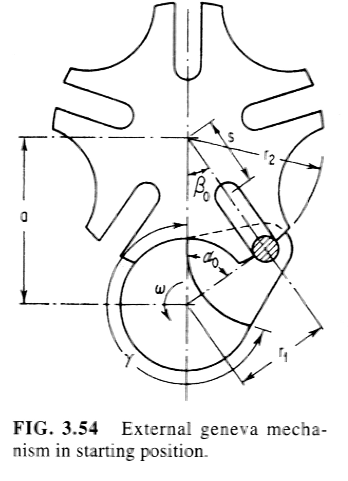
A Geneva Mechanism is a commonly used mechanism for producing an intermittent rotary motion from a uniform input speed. The driven member, or star wheel, contains evenly spaced slots into which the roller of the driving crank slides into. The number of slots determines the ratio between the dwell (stationary) and motion periods of the driven shaft. The mechanism requires a minimum of three slots to function and additional slots can be added.The motion of a Geneva Mechanism is represented in Figure 4. As the Drive wheel turns it enters the slots of the driven, or star, wheel and the mechanism enters its motion period. As the pin leaves the slot the driven wheel has been indexed and it continues to stay stationary until the pin rotates back around.
The different components of the device are provided in the BOM table
The Lesson Plan for the Geneva Mechanism is attached to this page for the Instructors who wish to teach students about this device.
Post Processing note: If you are printing with an FDM printer you should expect small ridges on parts where the extruder last touches the piece. Carefully inspect each piece after they are printed for these small imperfections as they will hinder the operation of your device.
Attachments
- LessonPlan_Geneva (1).docx
Teacher Notes
Teachers! Did you use this instructable in your classroom?
Add a Teacher Note to share how you incorporated it into your lesson.

Step 1: Print Geneva Mechanism Parts
Geneva Mechanism Design Equation and Calculator The Geneva Mechanism or Maltese cross is a gear mechanism that translates a continuous rotation movement into intermittent rotary motion. The rotating drive wheel is usually equipped with a pin that reaches into a slot located in the other wheel ( driven wheel ) that advances it by one step at a time.
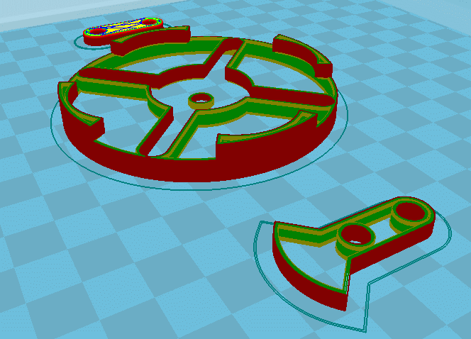
Download the 7 .stl files provided and upload them to your 3D printer's system. The quality of each part will increase depending on the orientation of the part on the print tray. Print each respective part in the following orientations;
1. Driving Disk (face down)
2. Output Disk (face down)
3. Driving Shaft (horizontal)
4. Output Shaft (horizontal)
5. Base (large face down)
6. Arrow Pin (face down)
7. Crank (horizontal)
Step 2: Post Processing Parts
Based on the brand and quality of your 3D printer, the tolerances of your parts will vary so your parts may not need any refinements, or they may need a lot. The steps we have provided are the techniques we found were useful for making the device run as smoothly as possible. The following tools were used to refine the parts; file (varying sizes), fine sandpaper, Dental picks.
For Geneva Mechanism:
Ensure to bore/file out any thru holes on the device to maximize the rotation ease. Ensure to sand the two shafts.
Step 3: Assembling the Device
 Now that all the parts are refined they are ready to be assembled to create the operational Geneva Mechanism.
Geneva Mechanism Slots
- Insert the Driving wheel over the thru hole on the main base
- Insert the Drive crank shaft through the Driving wheel and the main base
- Insert the Crank over the Drive crank shaft
- Insert the Arrow pin into the Drive crank shaft and the crank
- Insert the Driven wheel into the main base
- Insert the Driven shaft over thru hole on the main base
- Insert the Arrow pin into the Driven shaft retaining the Driven wheel

Be the First to Share
Recommendations
Geneva Mechanism Applications
Geneva Mechanism For Sale
Magnets Challenge
Snow Challenge
Wearables Contest